DC Motor Controller Design Principles Circuit Examples Circuit Diagram The interlock contacts installed in the previous section's motor control circuit work fine, but the motor will run only as long as each push button switch is held down.. If we wanted to keep the motor running even after the operator takes his or her hand off the control switch(es), we could change the circuit in a couple of different ways: we could replace the push button switches with
Basic Start/Stop Motor Control Circuit. This motor control circuit is an essential part of many industrial applications where the need for starting and stopping a motor is required. It provides a simple but effective way to control the motor's operation. The circuit consists of a Start button, a Stop button, a motor, and a power supply. They regulate the speed, direction, and starting/stopping of electric motors, ensuring efficient and safe operation. In this guide, we will explore different types of motor control circuits, including their wiring diagrams and key advantages and disadvantages. Types of Motor Control Circuits. Direct Online (DOL) Starter

5 Simple DC Motor Speed Controller Circuits Explained Circuit Diagram
Electric motor speed controller. In this video we learn how to design a simple PWM speed controller for a DC motor learning how current flows in the circuit
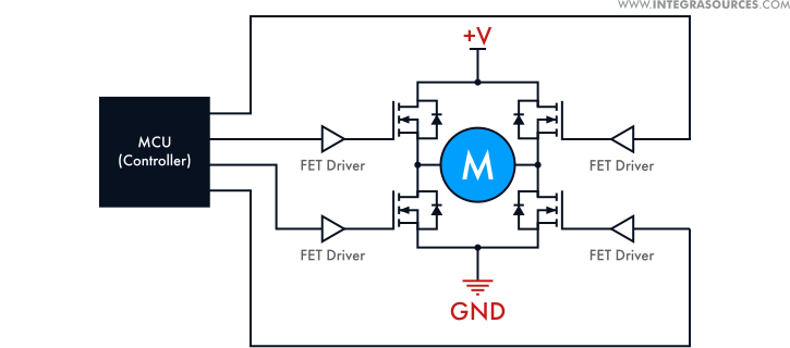
For instance, a DC motor controller for an industrial brushed motor uses different working principles and has a different design compared to a controller for DC motors in electric vehicles. All direct-current motors must have two core elements: a stator and a rotor (armature), although critical functions can be performed by other components as A GREAT resource on motors + motor control is Sang Hoon Kim's "Electric Motor Control" linked above. In the design of a motor controller, we need all the power electronics required to drive the motor phases of course, but we also need any hardware essential to measuring the key variables we need for performing the math for commutation After taking this course, you will be able to: Understand how to specify the proper AC or DC motor for a machine design. Integrate the motor to a machine, based on analysis of motor equations for voltage, current, torque and speed. Implement the motor and accompanying rotary sensor into a motor control circuit in both hardware and software. Add

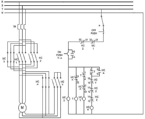
Phase Motor Control Diagram Circuit Diagram
Learn the basics of the electric motor speed controller. we learn how to design a simple PWM speed controller for a DC motor learning how current flows in the circuit and what each component does. a 555 timer, and we're going to show you how the circuit works, how to design one and even turn it into a professional looking printed circuit
